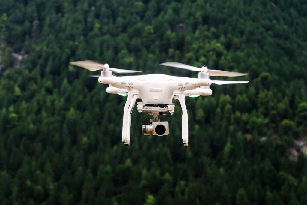

The first technical specification should be ground sampling distance, or GSD. It describes the amount of ground represented by one image pixel. A smaller GSD generally reveals finer features, but lower altitude also increases image count and may complicate safe coverage. A road widening project might need consistent detail along several kilometres rather than extreme resolution at one isolated junction. Narrow drainage channels, pavement cracks, and small stockpile changes can disappear if the aircraft flies too high. Before selecting altitude, the crew should record the target GSD in the mission plan and confirm that the camera, lens, and expected flying height can produce it. Teams arranging a drone survey should settle this requirement before accepting an attractive but unsuitable flight plan.
Overlap gives photogrammetry software the repeated visual information needed to match photographs and estimate camera positions. Front overlap refers to shared coverage along a flight line, while side overlap describes shared coverage between neighboring lines. The required settings depend on the terrain, camera, speed, and processing method, so the operator should use a mission plan suited to the site rather than relying on a familiar preset. Bare sand, glossy roofs, uniform concrete, and water provide limited texture. Moving trucks can also confuse image matching. After the first pass, the pilot should inspect sample photographs for blur, glare, exposure problems, and complete coverage instead of waiting for a failed block to appear during office processing.
Ground control points provide surveyed locations that connect the model to the physical site. They should be clearly visible in several photographs and distributed across the area, including near edges and across changes in elevation. Checkpoints, which are held out of the adjustment, provide an independent way to test the result. RTK and PPK can improve the recorded camera positions through correction data, but they do not eliminate errors caused by poor satellite visibility, misplaced targets, bad observations, or an incorrect coordinate reference system. A useful field habit is to photograph each target and note its identifier immediately. That small record prevents the processing team from guessing which mark belongs to which coordinate.
Terrain and structures determine whether a straight downward grid is sufficient. Nadir images are useful for plan maps, while oblique images can document slopes, walls, facades, tanks, and pipe racks. A steep excavation may need flight lines that follow its shape, and a narrow pipeline corridor may need more deliberate camera orientation than a flat open field. Tall objects can hide lower surfaces or create gaps in the model, particularly if the aircraft remains too far away. The operator should set routes and viewing angles around the inspection question, while maintaining safe separation from workers, vehicles, cranes, cables, and other obstacles. A site sketch marked with these hazards is often more useful than a generic checklist.
Light, wind, dust, and site activity can change the quality of otherwise well planned imagery. Strong shadows may hide edges, while glare from metal roofing or standing water can reduce useful texture. The crew should check the forecast and observe actual conditions before launch, because a clear morning can become a bright, windy afternoon. Camera focus, shutter speed, image format, and exposure settings should be checked against a few test images. The pilot should also confirm battery condition, storage capacity, return settings, and the planned emergency landing area. If earthmoving continues during capture, the flight log should record which machines were operating and the approximate time they crossed the survey area.
Processing is part of quality control rather than a final button press. A point cloud contains calculated three dimensional points that describe surfaces and can support terrain models, stockpile volumes, and progress comparisons. Vegetation, dust, glare, and moving equipment may create false points or obscure the ground. For example, a fill pile can appear to change size when trucks have crossed it between image sets. The reviewer should inspect camera alignment, coverage, control residuals, visible holes, seam errors, and unusual elevations before issuing measurements. Keeping the original images, flight log, control observations, and processing settings together makes it possible to trace a questionable result back to its source. Practical site inspection flight planning supports that record keeping before problems reach the client.
The handoff should state exactly what was captured and how the recipient can use it. Supply the map or model with its capture date, coordinate reference, coverage notes, processing method, resolution, and known exclusions. Repeat surveys should use comparable flight paths, camera settings, control arrangements, and review procedures; otherwise a difference may reflect data quality rather than construction progress. A supervisor may need an annotated image, while a surveyor may require elevations, a point cloud, or measurements in a specified coordinate system. Before full delivery, send a small sample for review. That check can expose a missing boundary, unsuitable detail, or misunderstood measurement requirement while the crew still has a realistic opportunity to return to the site.